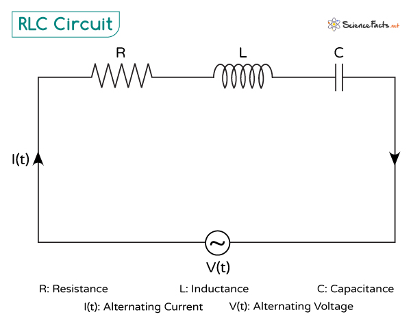
RLC Circuit
An RLC is an electrical circuit made up of three components: an inductor (L), which stores energy in a magnetic field; a resistor (R), which opposes the flow of current and dissipates energy as heat; and a capacitor (C), which stores energy in an electric field. These components can be connected in series or parallel in an alternating current (AC) circuit. Together, they affect the overall behavior of the circuit by controlling the flow of current, causing the circuit to exhibit a phenomenon known as resonance at a particular frequency where energy transfer is maximized.
Current and Voltage in an RLC Circuit
In an RLC circuit, the current and voltage behavior across each component is different due to the different ways each element interacts with the alternating current.
Resistor
The resistor follows Ohm’s Law, which is:
\[ V_R = I \cdot R \]
Where:
– VR is the voltage across the resistor
– I is the current through the circuit
– R is the resistance
The voltage and current are in phase, meaning they reach their maximum and minimum values simultaneously. There is no delay between the voltage and the current waveforms.
Inductor
The inductor stores energy in the form of a magnetic field when current flows through it. The voltage across an inductor depends on the rate at which the current changes. The inductor offers resistance to the current through a physical quantity known as inductive reactance. It is given by:
Where:
– XL is the inductive reactance
– f is the frequency of the AC signal in Hertz
– L is the inductance
The voltage is given by:
VL = I XL
In an inductor, voltage leads the current by 90 degrees. It means that the voltage across the inductor reaches its peak before the current does. This “lagging” current happens because the inductor resists changes in current flow; it takes time to build or collapse the magnetic field.
Capacitor
The capacitor stores energy in an electric field between its plates. The voltage across a capacitor is related to the amount of charge stored. The capacitive reactance of the capacitor is similar to the resistance of the resistor. It measures the opposition to the current flow:
Where:
– XC is the capacitive reactance
– C is the capacitance
The voltage is given by:
VC = I XC
In a capacitor, current leads the voltage by 90 degrees. It is the opposite of the inductor, where the voltage leads the current. Here, the current reaches its peak before the voltage does because the capacitor charges up as the current flows, but there is a delay before the voltage across the plates fully builds up.
The total current in an LRC circuit depends on the combined effects of the resistor’s resistance, the inductor’s inductive reactance, and the capacitor’s capacitive reactance. The impedance Z of the circuit determines how much current flows for a given voltage V(t):
\[ Z = \sqrt{R^2 + (X_L – X_C)^2} \]
Thus, the current I(t) is given by
I(t) = V(t)/Z
Resonance
In an LRC circuit, resonance occurs when the inductive reactance and capacitive reactance cancel each other out, allowing the circuit to achieve maximum energy transfer. Using the formulas for inductive and capacitive reactance:
At resonance, these equalize:
Solving for the resonance angular frequency \omega, we find:
The resonance frequency (in Hz) is given by:
\[ f_0 = \frac{1}{2\pi\sqrt{LC}} \]
This frequency is crucial in applications such as tuning radios, where the circuit selects the desired signal frequency while filtering out others. When resonance occurs, the impedance of the circuit is at its minimum, equal only to the resistance:
As impedance is minimized, the current in the circuit is maximized, following Ohm’s Law:
\[ I = \frac{V}{Z} \]
At resonance, the circuit allows the maximum amount of current to flow for a given voltage. This phenomenon is essential in tuning applications, where it is crucial to pick up or transmit signals at specific frequencies.
-
References
Article was last reviewed on Wednesday, October 30, 2024
Related articles


Join our Newsletter
Fill your E-mail Address