Inductance
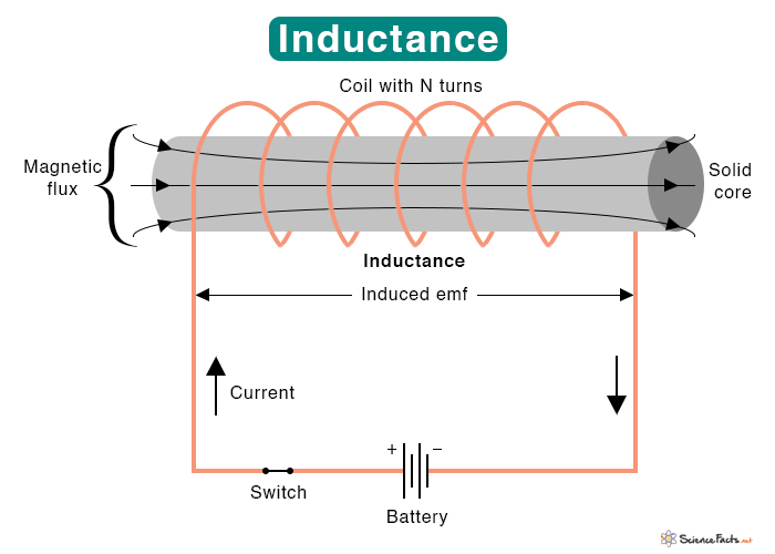
Inductance is a property of a conducting wire wound in the shape of a coil that opposes any change in the current flowing through it. According to Faraday’s law of electromagnetic induction, changing current induces an emf (electromotive force) in the coil. The magnitude of the emf is proportional to the rate of change of current. The proportionality constant is the inductance.
Inductance Formula
The inductance (L) is calculated from the ratio of the induced emf (ε) and the magnitude of the rate of current change (ΔI/Δt).
To measure the inductance, we use a device called an inductor in the electrical circuit. The SI unit of inductance is Henry or H, named after American scientist Joseph Henry. He discovered electromagnetic induction around 1831.
Inductance and Shape of Inductors
Inductors are designed to take advantage of inductance by taking the shape of a coil. This shape results in a stronger magnetic field than what would be produced by a straight wire.
Some inductors are made up of a single wire and are wound into a self-supporting coil. Other inductors consist of a wire wound into a coil around a long solid core, circular core, or rectangular core made of soft iron. A soft iron core chokes the current rise more effectively than air, increasing the inductance.
Types of Inductance
There are two ways in which inductance is used in an electrical circuit.
1. Self-Inductance
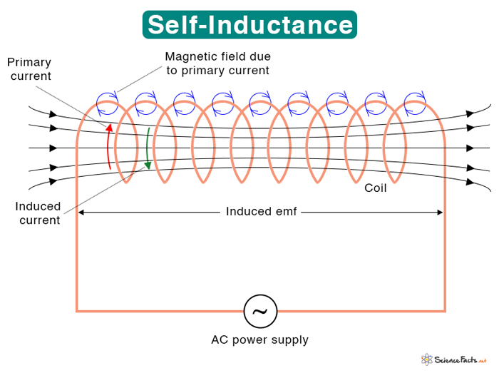
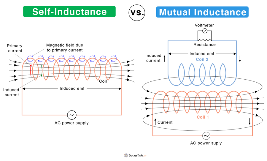
If the emf is induced in the same coil as the flowing current, it is known as self-inductance. An example of a device where self-inductance occurs is a choke. The symbol L denotes it.
Equation
The self-inductance L can be found in terms of the flux φ, number of turns of the coil N, and current I.
Using the above equation, the self-inductance can be calculated for the solenoid and toroid.
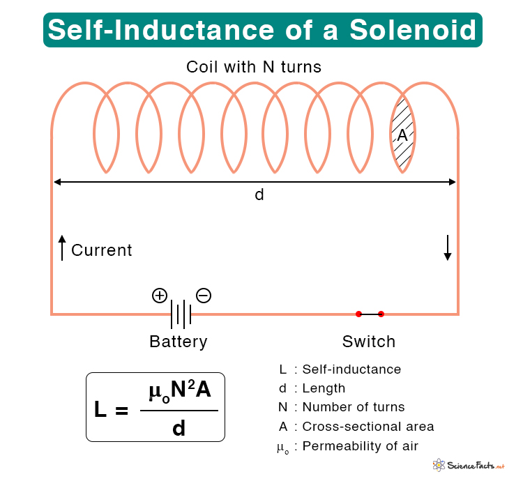
1. Solenoid
The following equation gives the self-inductance of a solenoid.
Where
N : Number of turns
A : Cross-sectional area
d : Length
μo: Permeability of air
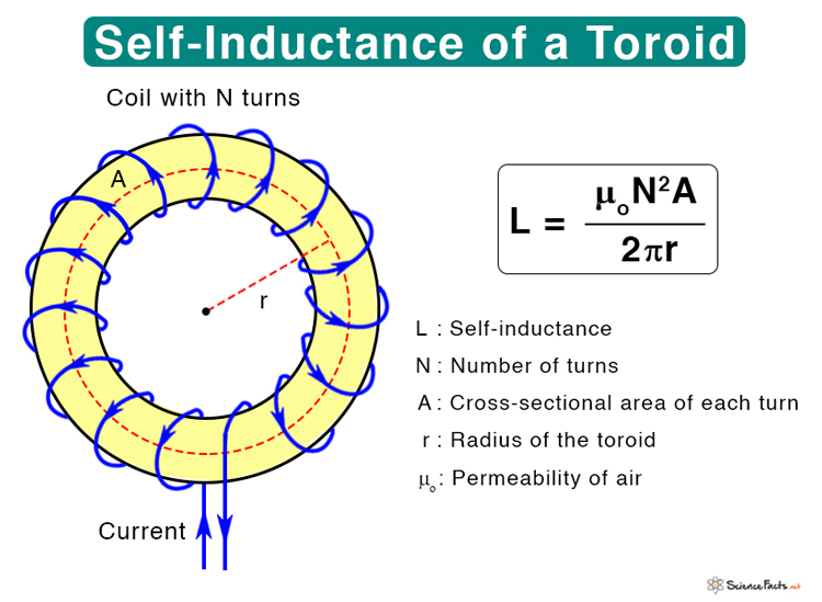
2. Toroid
The following equation gives the self-inductance of a toroid.
Where
N : Number of turns
A : Cross-sectional area
r : Radius of the toroid
μo: Permeability of air
Suppose the coil is wrapped around a solid core instead of a hollow one. In that case, air permeability is replaced by the permeability of the core material and denoted by μ.
2. Mutual Inductance
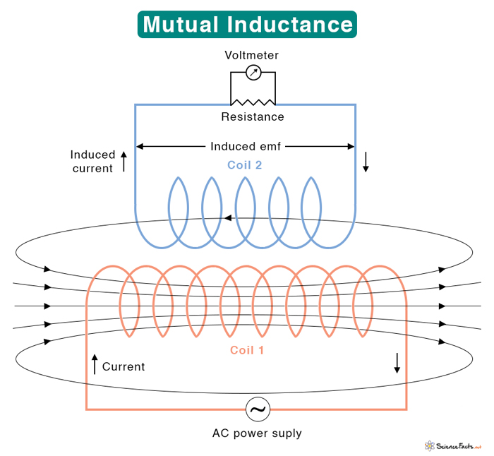
If the emf is produced in another coil placed next to the first, it is known as mutual inductance. Mutual inductance occurs in a transformer, generator, and motor. The symbol M denotes it.
Equation
Suppose the second coil has N2 turns and the flux passing through it due to current I1 in the first coil is φ21. The following equation gives the mutual inductance.
Based on the above equation, the mutual inductance can be calculated for different arrangements of coils.
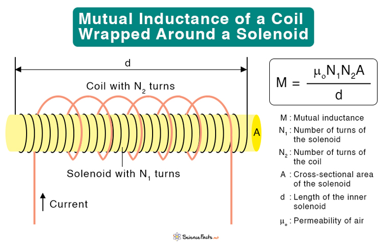
Mutual-inductance Between a Coil and a Solenoid
The following equation gives the mutual inductance of a coil wrapped around a solenoid.
Where
N1 : Number of turns of the solenoid
N2 : Number of turns of the coil
A : Cross-sectional area of the solenoid
d : Length of the solenoid
Factors Affecting Inductance
1. Length of the coil: It is inversely proportional to the length of the coil. If the length of the coil is increased, the inductance is reduced, and vice versa.
2. Cross-sectional area of the coil: It is directly proportional to the cross-sectional area of the coil. The higher the area of the coil, the higher the inductance.
3. Number of turns: It is directly proportional to the number of turns square. Hence, the higher the number of turns, the higher the inductance.
4. Permeability of the core: The permeability of the core material allows the magnetic field to form inside the core. The inductance is directly proportional to the permeability. The higher the permeability, the higher will be the inductance.
Uses and Applications
- To slow down current surges by temporarily storing electrical energy in an electromagnetic field and releasing it into the circuit
- To choke or block high-frequency noise in an electric circuit
- For storing and transferring energy in power converters, like dc-to-dc or ac-to-dc
- For selecting the desired frequency in a tuned circuit like an LC circuit
- To match the impedance of a power source to the impedance of an electrical load, known as impedance matching
- To amplify the current in a proximity sensor
What is the Difference Between Self-inductance and Mutual Inductance
| Self-inductance | Mutual Inductance | |
|---|---|---|
| Definition | The magnetic flux in a single-coil produces an emf that opposes the current flow | The magnetic flux links a pair of coils, and emf is produced in both coils that oppose the current flow in the other coil |
| What happens | The induced emf opposes the rise/fall of current when the current in the coil increases/decreases | The induced emf in the second coil opposes the rise/fall of current in the first coil when the current increases/decreases |
| Where it occurs | It takes place in a single coil, like a choke | It takes place in a pair of coils found in the transformer, generator, and motor |
| Symbol | L | M |
FAQs
Ans. When inductors are connected in series, the equivalent inductance is the sum of the individual inductances.
Ans. When inductors are connected in parallel, the total inductance is less than any one of the parallel inductors’ inductances.
Ans. The main difference between inductance and capacitance is that inductance is a property of a current-carrying conductor that generates a magnetic field around the conductor. On the other hand, capacitance is a device’s property that can hold and store electric charges.
Ans. Conductance is the property of a conductor that determines the flow of electrons through it. It is the opposite of resistance. Inductance is the property of a material that produces a magnetic field when current passes through it, resulting in an emf.
-
References
Article was last reviewed on Thursday, February 2, 2023



Thanks so much for providing essential information