Bridge Rectifier
A bridge rectifier is a type of full wave rectifier that converts AC signals into DC signals. An AC or alternating current flows in both directions, while a DC or direct current flows in one direction only. Therefore, by using both halves of the input, a bridge rectifier produces a smoother and more reliable DC output.
Construction
To construct a bridge rectifier, the following components are essential:
- Four diodes
- Load resistor
- AC source
Diode Bridge Configuration
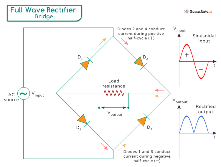
The image below shows a simple circuit diagram. The heart of the bridge rectifier is the arrangement of the four diodes (D1, D2, D3, and D4).
They are connected in such a way that they form a closed loop or a bridge:
AC Input: The AC supply is connected to two opposite corners of the diode bridge.
Diode Connections: The four diodes are arranged in a diamond shape, with the AC input connected to the two opposite corners of this diamond.
Output: The other two corners of the diamond connect to the load resistor, where the DC output is taken.
Working
Positive Half-Cycle
When AC voltage is applied to the bridge rectifier, it oscillates between positive and negative values. During the positive half-cycle of the AC input, the following observations are made:
Current Flow
The AC voltage causes the diodes D2 and D4 to become forward biased, meaning they allow current to pass through them. At the same time, diodes D1 and D3 become reverse-biased, so they block the current.
Current Path
The current flows from the positive terminal of the AC source through D2. Then, it flows across the load resistor, then through D4, and back to the negative terminal of the AC source.
Output Voltage
As the current flows through the load resistor, it creates a positive voltage across the load. This positive voltage is what we want for DC power.
Negative Half-Cycle
During the negative half-cycle of the AC input, the role of the diodes switches, and we observe the following:
Current Flow
The AC voltage now causes diodes D1 and D3 to become forward biased, allowing current to flow through them. Diodes D2 and D4 become reverse biased and block the current.
Current Path
Current flows from the negative terminal of the AC source through diode D3, across the load resistor, then through diode D1, and back to the positive terminal of the AC source.
Output Voltage
Even though the input AC voltage is negative during this half-cycle, the arrangement of the diodes ensures that the current still flows in the same direction through the load resistor. It again produces a positive voltage across the load.
Thus, the diodes work together to direct the current in the same direction during both halves of the AC cycle.
It results in a pulsating DC output, which is not perfectly smooth but is much closer to the DC needed for most electronic devices. The pulsations are known as “ripples”. While they are not ideal, they can be reduced or smoothed out using additional components, like capacitors.
Advantages
- Efficient Full-Wave Rectification: A bridge rectifier converts both halves of the AC input waveform into DC, doubling the output frequency, increasing the average output voltage, and reducing energy waste, making it ideal for applications requiring high efficiency and power.
- Reduced Ripple and Smoother Output: Bridge rectifiers produce a higher frequency pulsating DC, leading to lower ripple amplitude and a more stable, smoother DC output, which is easier to filter and ideal for powering sensitive electronics.
- Compact, Reliable, and Cost-Effective Design: Bridge rectifiers are compact and integrate easily into small devices, offering reliability with minimal maintenance and cost-effectiveness, making them suitable for a wide range of applications, from consumer electronics to industrial equipment.
-
References
Article was last reviewed on Thursday, August 22, 2024
Related articles


Join our Newsletter
Fill your E-mail Address